Postby rado » September 1st, 2010, 3:32 pm
What’s involved in Flow Bench aided head porting?
Make no mistake, head porting (done the right way) is far more science than it is art! The purpose of this short article is to share the correct approach, and some details of the work required in professional head porting.
The science analogy is a good fit because of the methods required, and the key role that accuracy and measurement plays in delivering consistently good results. At Precision Performance we’re after real world performance… no more guess work! You can think about it this way… would you hire a contractor to build your home if he told you he did not need a measuring tape or a level?
Cleanup and Baseline flow mapping
So where do we start? Well first the head has to be cleaned and disassembled. Then we set it up on the bench to map out baseline, or stock flow characteristics. Each head is different and further, on the same head, you can have differences from port to port, by design or because of core shift during casting, so these must be taken into consideration when porting. I’ll talk a bit more about directional ports later on.
I should also mention that flow mapping requires the use of a jig capable of raising the intake or exhaust valves, in measured discrete increments. So flow mapping is not just about max flow, it describes flow throughout the lift range of the valves.
Enhancing flow
The process of removing material is guided by several factors including
• The purpose the head is to be used for.
• Information available on that type of head (Flow tables, porting & valve seat analysis etc.)
• Best practice in porting
o Don’t ever remove material when it does not benefit flow! It takes very little effort to “muck up” some heads! Further, some ports are directional and channel air in such a manner to promote “swirl” or “tumble”. So you DON’T try to “straighten” ports that are not so designed!
o Focus on the point of greatest restriction
o Determine the natural air path within the port and make accommodations to enhance flow.
o Finally, a port does not have to look pretty to flow well. Your eyes do not work with the same rules as air does!
What to look at
There are three variables we pay attention to when porting a head:
• Flow Quantity
• Flow Velocity
• Flow Quality.
We measure quantity on the flow bench in CFM or cubic feet per minute. As may know, if you gain CFM at the expense of velocity (FPS… feet per second) you can actually end up with a port that performs worse than stock. Velocity is measured on the bench with a device known as a pitot tube.
Flow quality is a measure of turbulence. While we do not have equipment to measure turbulence directly, FPS is directly correlated, and simple aerodynamics and fluid dynamics principles guide in this regard.
The process is classic stepwise refinement which may involve many rotations between the bench and the porting station in order to get optimum results. This job is not for the hasty; much patience is required when specific guiding data is not available.
Port Mapping & Replication
So, you’ve achieved a significant gain in flow without sacrificing velocity! Great! Now how do you translate this to all the ports? Since computer numeric control (CNC) only makes sense in large scale operations, caliper measurements in all the critical areas must suffice. This allows specific port shapes to be translated in all ports across the head. Just multiply the work for one by as many chambers on the head!
Seat preparation
Now we turn our attention to the all important valve seats. This is another area where science rules. Just because the traditional 30, 45, 60 works fine for engine X does not mean it will perform the same on engine Y. I cannot stress enough the importance of quantitative performance data in this regard.
At Precision Performance, there are two options. Maintain the original port configuration with valve lapping, or opt for multi angle valve configurations, which promote flow and sealing. If you’re interested in oversized valves, then seat grinding is a must, and over-sizing will be limited by the width of the stock seats, or aftermarket inserts that you may have installed elsewhere.
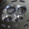
The valve seat and chamber, and bowl are the most critical areas in any porting job! Just multiply the work for one seat by sixteen for four cylinder multi valve motors.
Valve preparation
After significant mileage, even in good working engines, the valve facing will begin to pit and sealing with the seat will be compromised. Valve re-facing is an option here along with back cutting which can increase low lift flow in some applications. Let me state categorically, lapping valves will never be my first choice since many tuners agree that even though thoroughly cleaned, some of the lapping compound imbeds itself in the valve face and can lead to pre-mature wear. Accurate carbide cutters for the valve and seats are the way to go. Again multiply to work for one, by sixteen!
Finishing / Re-assembly.
Now we put it all together, and return the customer’s cylinder head for re-surfacing and assembly. Replacing valve seals is advised, but not always essential based on the mileage of the engine. It’s just one of those cheap insurance things that it’s better to do than not.
Soon I’ll post up some figures, with a brief analysis on a couple heads I’ve done some work on; since I’m sure there will be some curiosity.
Last edited by
rado on September 8th, 2011, 5:15 pm, edited 8 times in total.